27 Results
View results:
Sort by:

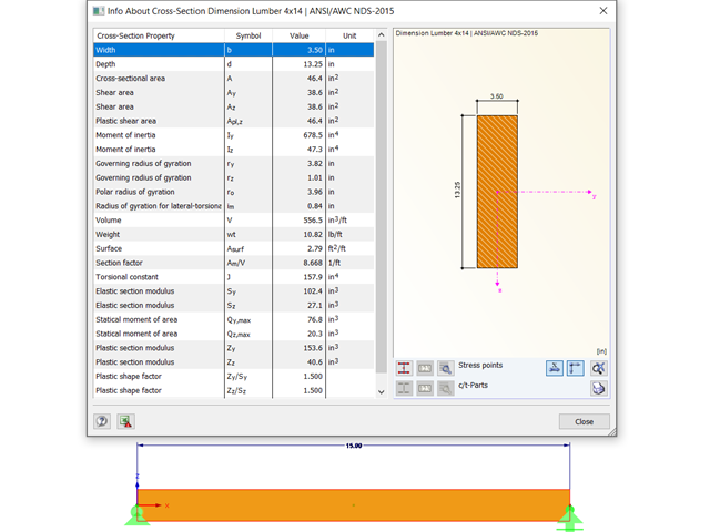
Using the Timber Design add-on, timber column design is possible according to the 2018 NDS standard ASD method. Accurately calculating timber member compressive capacity and adjustment factors is important for safety considerations and design. The following article will verify the maximum critical buckling strength calculated by the Timber Design add-on using step-by-step analytical equations as per the NDS 2018 standard including the compressive adjustment factors, adjusted compressive design value, and final design ratio.

Creating a validation example for Computational Fluid Dynamics (CFD) is a critical step in ensuring the accuracy and reliability of simulation results. This process involves comparing the outcomes of CFD simulations with experimental or analytical data from real-world scenarios. The objective is to establish that the CFD model can faithfully replicate the physical phenomena it is intended to simulate. This guide outlines the essential steps in developing a validation example for CFD simulation, from selecting a suitable physical scenario to analyzing and comparing the results. By meticulously following these steps, engineers and researchers can enhance the credibility of their CFD models, paving the way for their effective application in diverse fields such as aerodynamics, aerospace, and environmental studies.

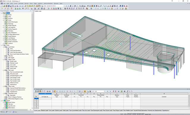
When it comes to wind loads on building type structures as per ASCE 7, numerous resources can be found to supplement design standards and aid engineers with this lateral load application. However, engineers may find it more difficult to find similar resources for wind loading on non-building type structures. This article will examine the steps to calculate and apply wind loads as per ASCE 7-22 on a circular reinforced concrete tank with a dome roof.

The goal of using the RFEM 6 and Blender with the Bullet Constraints Builder add-on is to obtain a graphical representation of the collapse of a model based on real data of physical properties. RFEM 6 serves as the source of geometry and data for the simulation. This is another example of why it is important to maintain our programs as so-called BIM Open, in order to achieve collaboration across software domains.

Using the Concrete Design add-on, concrete column design is possible according to ACI 318-19. The following article will confirm the reinforcement design of the Concrete Design add-on using step-by-step analytical equations as per the ACI 318-19 standard, including the required longitudinal steel reinforcement, gross cross-sectional area, and tie size/spacing.

The Construction Stages Analysis (CSA) add-on allows for the design of member, surface, and solid structures in RFEM 6 considering the specific construction stages associated with the construction process. This is important since buildings are not constructed all at once, but by gradually combining individual structural parts. The single steps in which structural elements, as well as loads, are added to the building are called construction stages, whereas the process itself is called a construction process.
Thus, the final state of the structure is available upon completion of the construction process; that is, all the construction stages. For some structures, the influence of the construction process (that is, all the individual construction stages) might be significant and it should be considered so that errors in the calculation are avoided. A general overview of the CSA add-on is given in the Knowledge Base article titled “Consideration of Construction Stages in RFEM 6”.

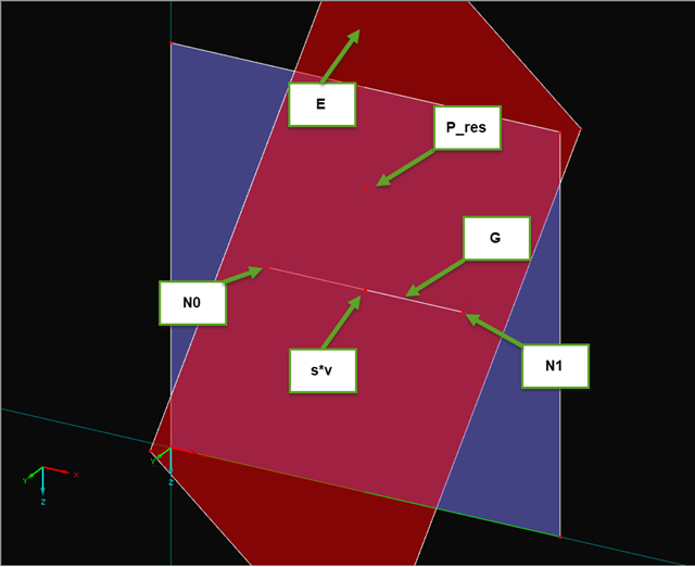
With the orthotropic elastic-plastic material model, you can calculate solids with plastic material properties in RFEM 5 and evaluate them according to the Tsai‑Wu failure criterion. The Tsai-Wu criterion is named for Stephen W. Tsai and Edward M. Wu, who published it in 1971 for plane stress states.
If the calculation of a member model according to the second-order analysis is terminated with an error message, this instability is often caused by failed tension members: As soon as compressive forces appear in a tension member during a calculation step, this member is no longer considered in the following iterations. Thus, the model can become unstable.

Using the RF-TIMBER CSA module, timber column design is possible according to the CSA O86-19 standard. Accurately calculating timber member compressive resistance and adjustment factors is important for safety considerations and design. The following article will verify the factored compressive resistance in the RFEM add-on module RF-TIMBER CSA, using step-by-step analytical equations as per the CSA O86-19 standard including the column modification factors, factored compressive resistance, and final design ratio.

Using the RF-TIMBER AWC module, timber column design is possible according to the 2018 NDS standard ASD method. Accurately calculating timber member compressive capacity and adjustment factors is important for safety considerations and design. The following article will verify the maximum critical buckling in RF-TIMBER AWC using step-by-step analytical equations as per the NDS 2018 standard including the compressive adjustment factors, adjusted compressive design value, and final design ratio.
If you read out the results of a surface by means of the COM interface, you get a one-dimensional field with all results at the FE nodes or grid points. To get the results on the edge of a surface or along a line within the surfaces, you have to filter out the results in the area of the line. The following article describes a function for this step.

Using the RF-TIMBER CSA module, timber beam design is possible according to the CSA O86-14 standard. Accurately calculating timber member bending resistance and adjustment factors is important for safety considerations and design. The following article will verify the factored bending moment resistance in the RFEM add-on module RF-TIMBER CSA using step-by-step analytical equations as per the CSA O86-14 standard including the bending modification factors, factored bending moment resistance, and final design ratio.
Using the RF-TIMBER AWC module, timber beam design is possible according to the 2018 NDS standard ASD method. Accurately calculating timber member bending capacity and adjustment factors is important for safety considerations and design. The following article will verify the maximum critical buckling in RF-TIMBER AWC using step-by-step analytical equations as per the NDS 2018 standard, including the bending adjustment factors, adjusted bending design value, and final design ratio.

Using RF-CONCRETE Members, concrete column design is possible according to ACI 318-14. Accurately designing concrete column shear and longitudinal reinforcement is important for safety considerations. The following article will confirm the reinforcement design in RF-CONCRETE Members using step-by-step analytical equations as per the ACI 318-14 standard, including required longitudinal steel reinforcement, gross cross-sectional area, and tie size/spacing.
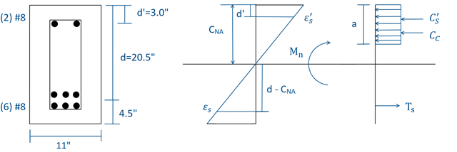
Using RF-CONCRETE Members, concrete beam design is possible according to ACI 318-14. Accurately designing concrete beam tension, compression, and shear reinforcement is important for safety considerations. The following article will confirm the reinforcement design in RF-CONCRETE Members using step-by-step analytical equations as per the ACI 318-14 standard, including moment strength, shear strength, and required reinforcement. The doubly reinforced concrete beam example analyzed includes shear reinforcement and will be designed under the ultimate limit state (ULS) design.
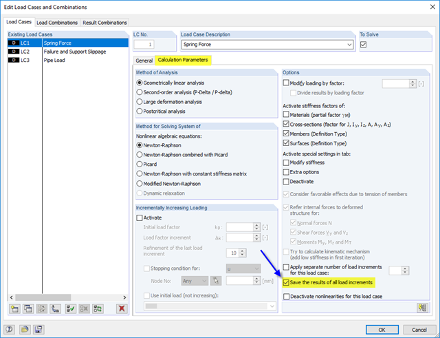
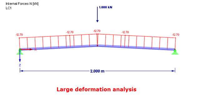
The calculation in RFEM is usually carried out in several calculation steps (iterations). It is then possible to consider particular characteristics of the model, such as objects with nonlinear functions. In addition, by using the iterative calculation, nonlinear effects are taken into account that result from changes in deformation and internal forces in case of the second-order analysis or when considering large deformations (cable theory). In case of complex models, geometric linear calculations are usually insufficient.

When it comes to wind loads on building type structures as per ASCE 7, numerous resources can be found to supplement design standards and aid engineers with this lateral load application. However, engineers may find it more difficult to find similar resources for wind loading on non-building type structures. This article will examine the steps to calculate and apply wind loads as per ASCE 7-16 on a circular reinforced concrete tank with a dome roof.
The efficient design of prestressed structural components requires a few additional steps that go beyond the standard reinforced concrete design, from modeling tendons to the calculation of equivalent loads to the cross-section resistance design. Therefore, it is important that the software for prestressed concrete design is structured and the navigation is possible in the program. RFEM with two add-on modules RF-TENDON and RF-TENDON Design fulfills these requirements and allows engineers to carry out the complete design of prestressed beams, frames, plates, buildings and bridges according to EN 1992-1-1 with National Annexes and SIA 262.
In the case of a post-critical failure, a substantial change occurs in the geometry of a structure. After reaching the instability of the equilibrium, a stable, strength position is reached again. The post-critical analysis requires an experimental approach. It is necessary to manually load the structure in increments step by step.
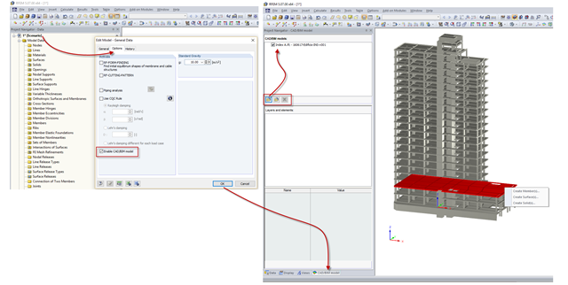
RFEM and RSTAB provide the option to "Enable CAD/BIM model" in the model's General Data dialog box, "Options" tab. In addition to creating a model as usual, this CAD/BIM model allows you to import, organize, and transform IFC, STEP, and IGES files.

The following article describes the design of a single-span beam subjected to bending and compression, which is performed according to EN 1993‑1‑1 in the RF-/STEEL EC3 add-on module. Since the beam is modeled with a tapered cross-section and thus it is not a uniform structural component, the design must be performed either according to General Method in compliance with Sect. 6.3.4 of EN 1993‑1‑1, or according to the second-order analysis. Both options will be explained and compared, and for the calculation according to the second-order analysis, there is an additional design format using Partial Internal Forces Method (PIFM) available. Therefore, the design is divided into three steps: design according to Sect. 6.3.4 of EN 1993‑1‑1 (General Method), design according to the second‑order analysis, elastic (warping torsion analysis), design according to the second‑order analysis, plastic (warping torsion analysis and Partial Internal Forces Method).
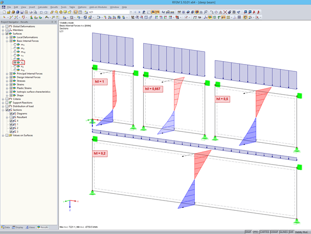
When analyzing structural components of reinforced concrete structures, it is often necessary to design deep beams. These are mainly used for window and door lintels, upstand and downstand beams, the connection between split-level slabs, and frame systems. If they are displayed as surfaces in RFEM, the evaluation of reinforcement results requires further steps.
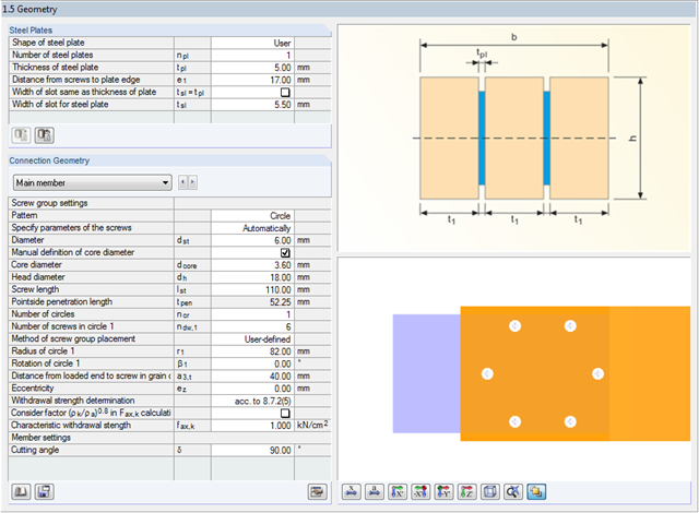
In RF-/JOINTS Timber – Steel to Timber, you can select a circular connection type for the dowel, bolt, nail, and screw joint categories. For this connection type, the minimum radius is set in compliance with the recommendations of the STEP-1 report of the German Information Service Timber.
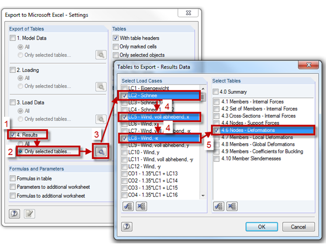
RFEM and RSTAB provide the export interface ("File" → "Export") to export model and load data, as well as results, to Excel or in a CSV file in one step. You can select the tables to be exported in the "Export Tables" section. The "Only selected tables" option allows you to export only a specific selection of tables. Use the [Select Load Cases and Tables for Export] button to open the corresponding dialog box.
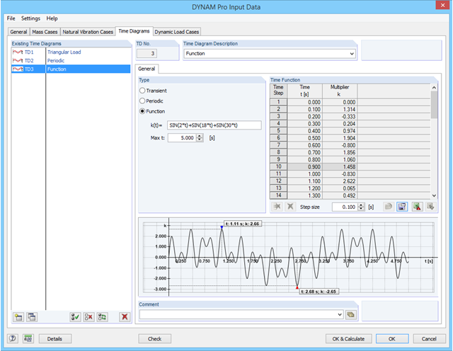
In RF-/DYNAM Pro - Forced Vibrations, you can define time diagrams directly as functions in an edit field. The parameter t is reserved for the time steps, but apart from that, all parameters as defined in the "Edit Parameter" dialog can be used in RF‑/DYNAM Pro.
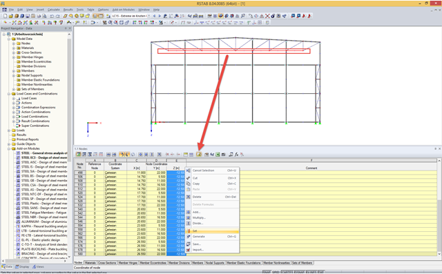
In addition to the standard functions, the input tables of the main program have block functions. With these functions, you can edit the data in the selected rows and columns of the table in one step.
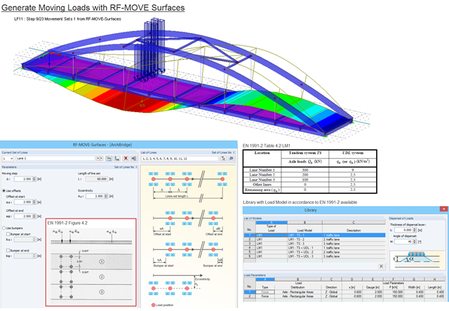
Moving loads can be generated easily with RF‑MOVE Surfaces. A library is available with load models as defined in Eurocode 1, Part 2. The input of step size, offsets at start and end, and the distance to a reference line make it possible for the user to generate user‑defined load models and influence the number of load cases generated. RF‑MOVE Surfaces generates load cases and, optionally, a result combination as an envelope of all results.